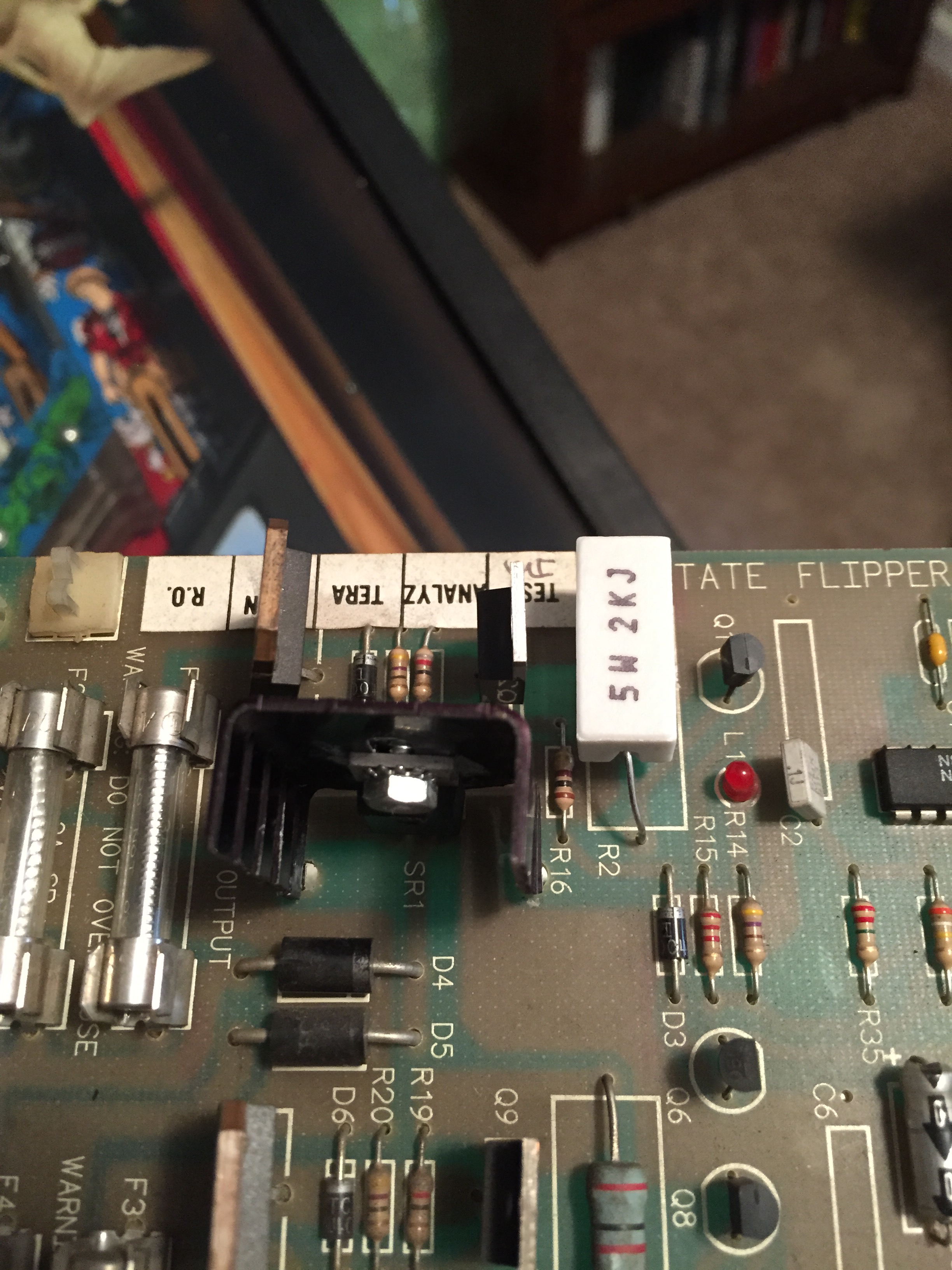
Did a flipper rebuild on a Data East Hook not too long ago and afterwards was having a hold problem on the right flipper. Went to check the fuse on the flipper power board and it was fine, but had found some rather shoddy previous work on the board.
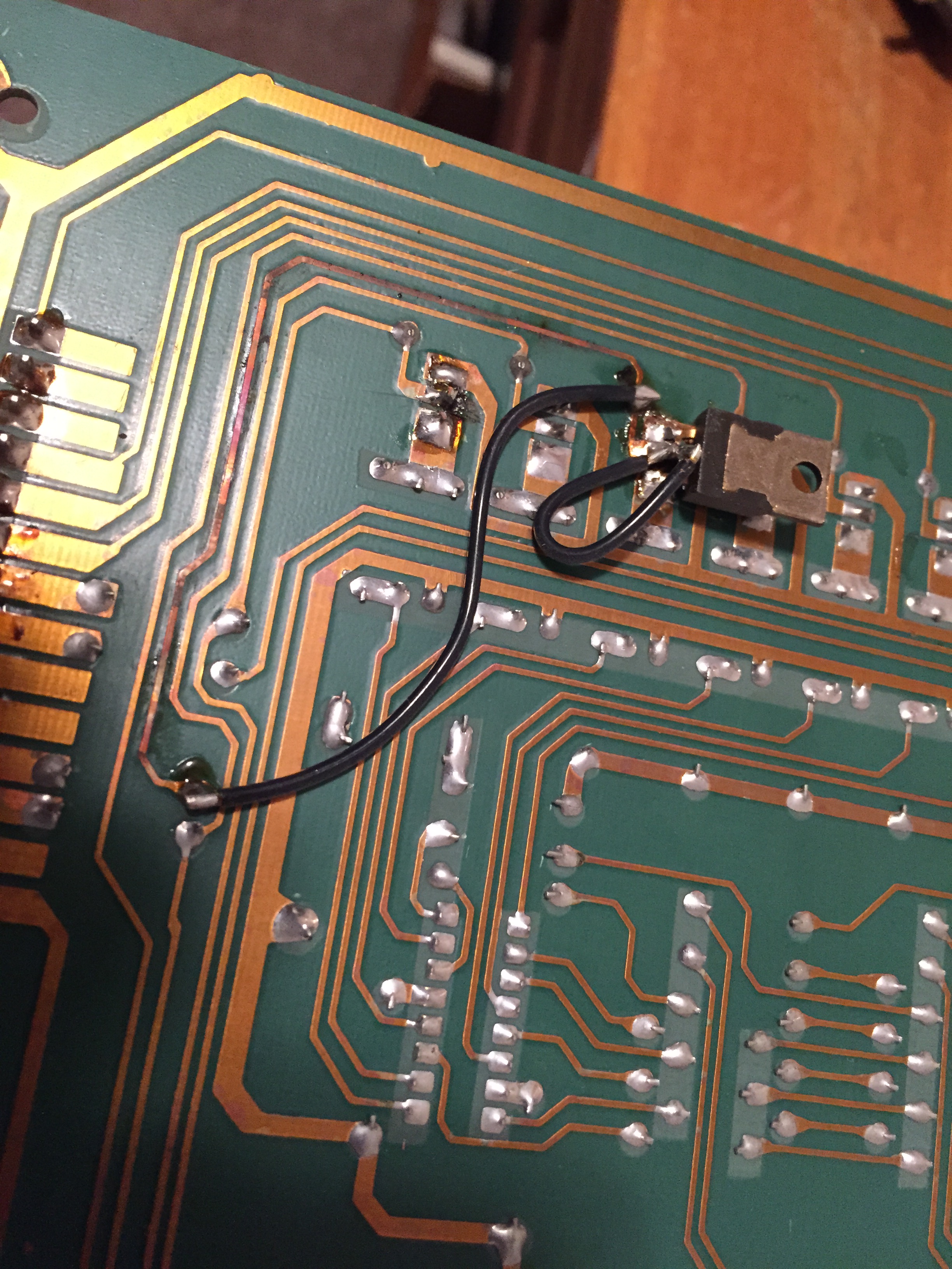
The T-800 triac had at one point been replaced and rather than putting back in the board appropriately, they had soldered it on the back of the board along with the heatsink bent in around it. It was pressed up against the cab and, over time, had caused one leg to come loose.
Replaced T-800 triac, TIP32C and 2k ohm resistor. T-800 relocated along with heatsink to proper position on the board.
Wish I had taken a picture of its original state, but I forgot so only have the cleaned up version. Anyway, once on the bench, I’d also noticed one leg of the 2000 ohm resistor in line with that triac had also come off and the issue had caused the TIP32C to short out as well.
I replaced all three components and put the T-800 triac back on the proper side of the board so that it could screw in right on the side of the cabinet where these Data East flipper power boards should.
Unfortunately, wasn’t able to test this one in game as this was for a two flip game and both of my Data East machines are three flips, but got a text later in the evening after the owner had picked up the board that everything was back working perfectly.
One thing I’ve done a lot of recently that I wanted to write up a quick post on is the Bally Solenoid Driver Board from Bally games manufactured from 1977-84. I have done the recommended upgrades and repaired four of these over the past month or so. The games I’ve done them on have been KISS, Paragon, Bobby Orr’s Power Play and Strikes and Spares.
This board is responsible for driving the under playfield solenoids and relays, regulating the high voltage for the displays and regulating the 5vdc logic voltage that is supplied to the rest of the boards.
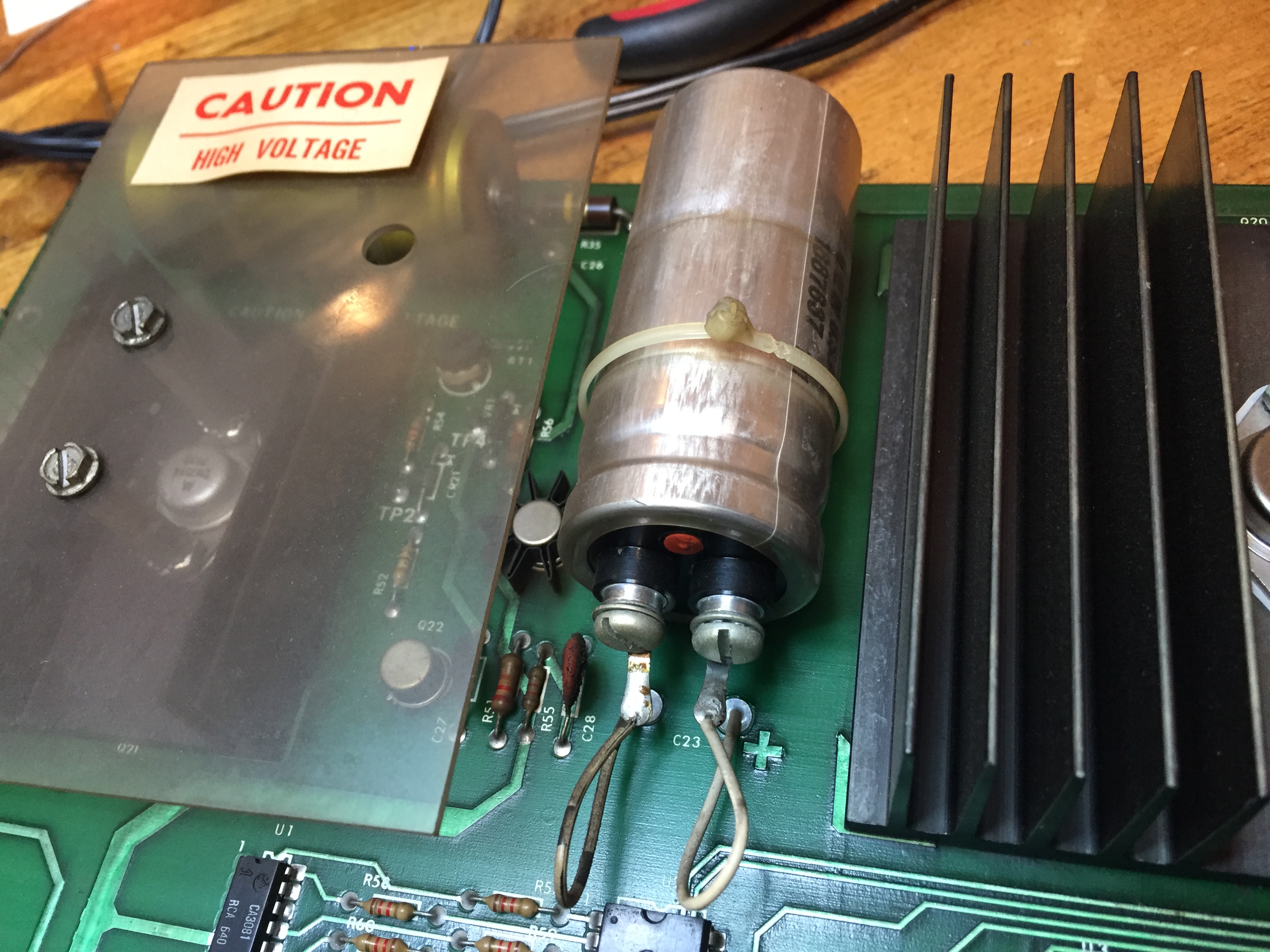
Original C23 — over 30 years old, needs replacement!
The first thing I always do is replace the C23 filter capacitor, which is the largest cap on the board. This cap is the one that filters the 5vdc logic, so its very important that it functions correctly. Most caps have a lifespan of about 10-15 years; with these games being over 30 years old, if that original capacitor is still on the board, it’s high time for a new one!
The other two modifications that are important for this board are: tying the negative lead of the replaced C23 capacitor to ground, and tying a jumper between TP1 and TP3.
While I have the board out, I always test all the transistors down the line to make sure they
Jumper on solder side of TP1 to TP3.
are all good to go. Testing the TIP120 transistors is easy, just set your DMM to the diode setting, put the black lead on the large metal tab of the transistor and then the red lead on each of the side legs. Each leg should read .4 to .6 volts, any reading outside of this range means a failed transistor. If you do find a failed transistor, I recommend replacing the original failed TIP 120 with the sturdier TIP 102 transistor.
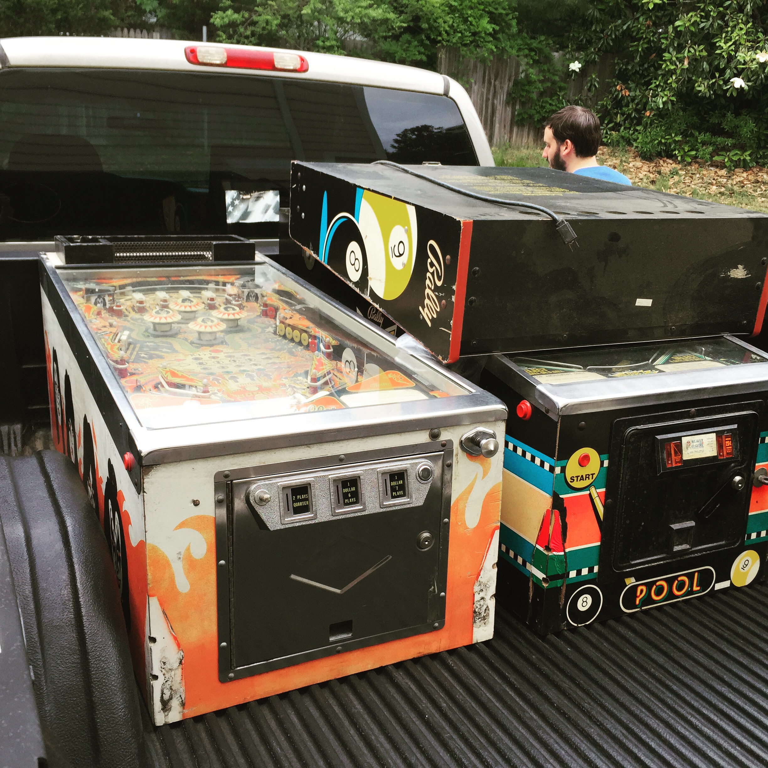
KISS and Pool Sharks on the truck before being unloaded
So, I picked up a 1979 Bally KISS pinball machine the other weekend along with the Pool Sharks. Overall the game was in pretty nice shape, but did need a little attention both electronically and cosmetically to get up to speed.
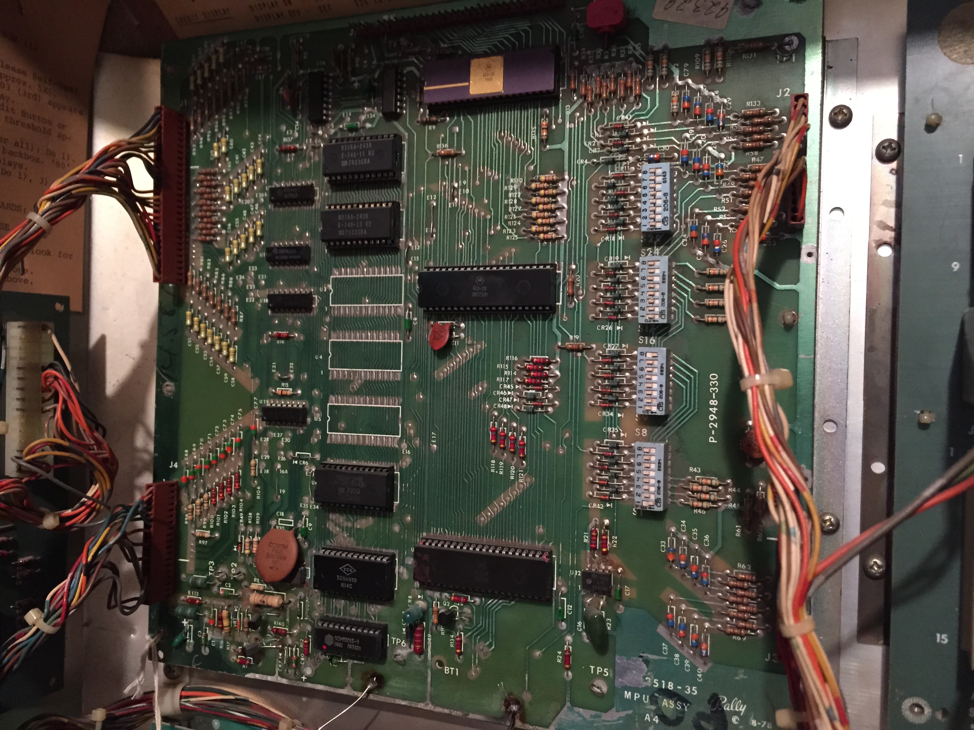
A good deal of the time you run into a corroded MPU on these Bally -17 and -35 games, but luckily, this game had a clean MPU; however, the original Ni-Cad battery was still attached to the board. First thing I did when I got it in the house was cut that Ni-Cad off — it’s amazing that thing hadn’t leaked in 36 years. Really, it’s just a roll of the dice when you find one like that. I had a Bally Frontier that similarly had the Ni-Cad still attached but a clean board, but those have been the only two I’ve seen so far.
MPU, remote pack attached on bottom of board.
After cutting the Ni-Cad battery off the MPU, I added a remote battery pack. The original Ni-Cad’s were rechargeable batteries, so when you add a 3 AA remote pack you have to put a blocking diode in line with the anode to prevent the charge coming back to the non-rechargeable batteries.
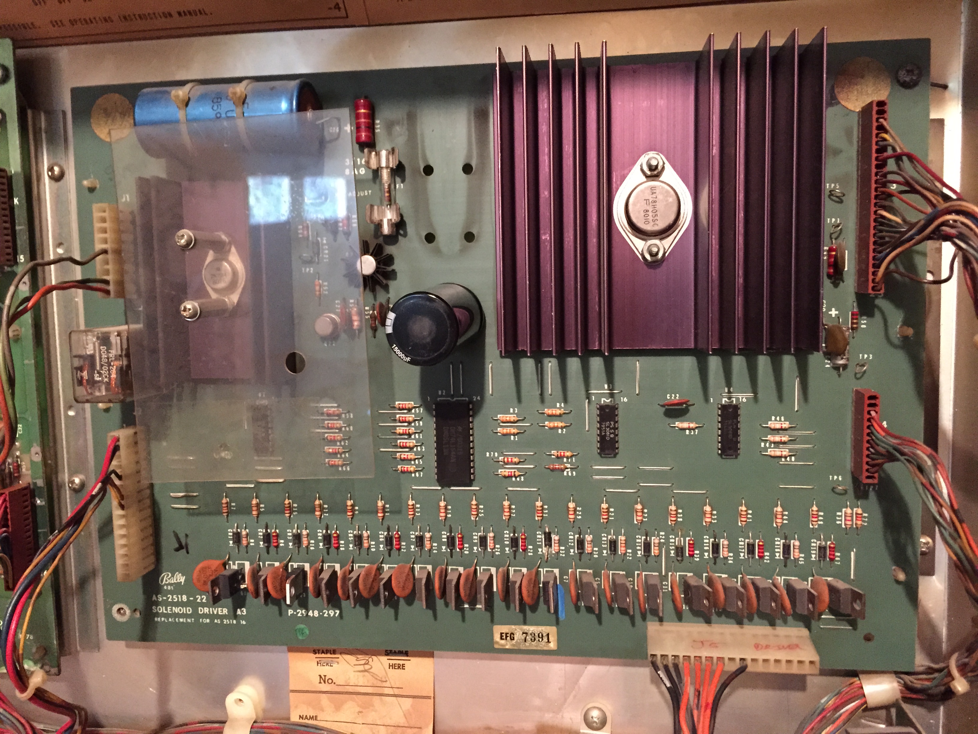
The second bit of board business was bringing some attention to the solenoid driver board. This board controls the display power regulation, as well as the transistors that fire all of the solenoids. When I pulled the board out, I immediately noticed a pretty terrible hack from earlier in the game’s life.
Hacked Transistor
One of the transistors had been replaced on the solder side of the board and the previous tech had damaged the through holes and run some jumpers. One of which wasn’t too bad, the other which was pretty shoddy. Having this transistor on the solder side of the board was a terrible idea because it could easily ground out against the ground plane behind the board and short out all over again. I replaced this transistor with a TIP102 on the proper side of the board. I ended up having to keep one of the jumpers on the solder side, but was able to bypass the other.
On all solenoid driver boards from this Bally era, I replace the large C23 capacitor that filters the 5VDC. The original capacitor was a 11,000 uf 20 volt, but you can replace with both a larger micro farad and voltage rating. I have found some reasonably priced 15,o00uf 25 volt caps from http://www.greatplainselectronics.com that fit nicely as a replacement.
After that, I did the two recommended modifications on this board which are: running a jumper from the negative lead of C23 to the trace right below it (on later -35 boards) and running a jumper between TP1 and TP3.
Finished Solenoid Driver Board. Note replaced C23 cap. Other modifications and transitor clean-up on back of the board.
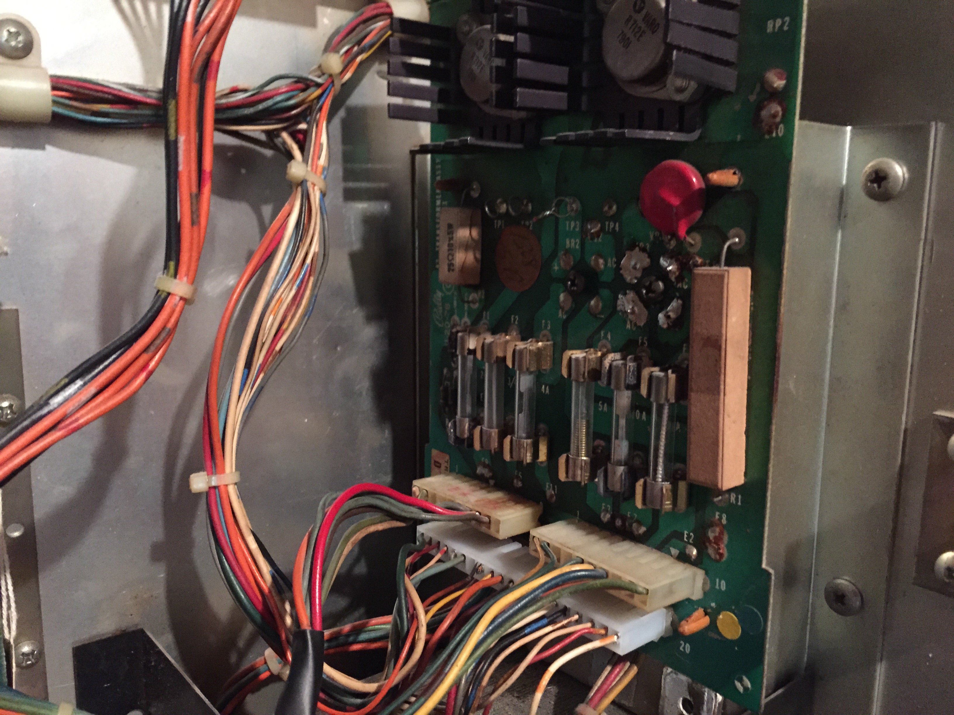
The other board related issue that I addressed was replacing the large 20-pin connector on the power supply/regulator board. It had, over time, gotten very brittle and actually split in two. One wire was even soldered directly onto the male pin and one side of the split was very burnt and brittle. I added in a new female molex 20 pin connector with sturdier trifurcon crimp connectors. This got everything booting and working. Only other functional issue I ran into was a
Replaced 20-pin connector on Power Supply/Regulator board.
stuck switch at switch 19 which ended up being a bad switch capacitor.
With the game working, I began the clean up and shop out. I cleaned the playfield which had a layer of dirt/dust over it, and then followed up with a good, hard layer of carnuba gold class paste wax to help protect the field during future play. I replaced the star posts with new red star posts, added orange super bands, replaced all white rubbers, cleaned the plastics, added LEDs in the GI, adjusted and cleaned all switch contacts, added a new ball and have tombstone KISS face drop targets on order. The targets are the only thing I am waiting on.
This is the first time I’ve really gotten to spend much time on a KISS game. I think the rules and gameplay are fantastic. It’s a fast and furious game, and the ruleset is simple but challenging. I can see why this game was so popular and sold 17,000 units.
On the home front, I’m still working through the final touches on the Bobby Orr Power Play machine, and should have have a couple of posts up soon on stuff I’ve done since working on it including some work, recommended modifications and new cap on the solenoid driver board.
In the meantime, I’ve also acquired a 1980 Stern Seawitch which I’ll be going through and fixing up, as well as a 1988 Williams Banzai Run in my personal collection which has a good amount of work to get through to be up to speed. And, just yesterday, I picked up a 1979 Bally KISS and a 1990 Bally Pool Sharks.
KISS and Pool Sharks on the truck before being unloaded
I started in on some of the surface point issues on Pool Sharks this evening. The game was playable when I got it and very little really that needs to be done, but I still like to go through and make sure everything is up to my standards.
First thing I noticed was that the ground prong was long gone on the AC cord, which is something that should be addressed on any machine. I used up my last three prong replacement connector on it this evening, so I’ll be off to Ace Hardware to restock on those shortly. I have some detailed information on how best to tackle adding on a three-prong connector in the Sorcerer post.
I’d say 85% of machines I come into contact with began their lives on route; meaning, an operator bought the game new and put it on location in a pub, gas station, etc. to make money. Over time, these machines have migrated into home use.
This machine was purchased from a private seller, but retained the common badge of its previous life on route on both the coin door and the backglass. Having an operator’s badge on the coin door doesn’t bother me too much; in fact, I think it kind of adds to the history of the game and lets you know where it came from more or less, but I can’t stand them on the backglass.
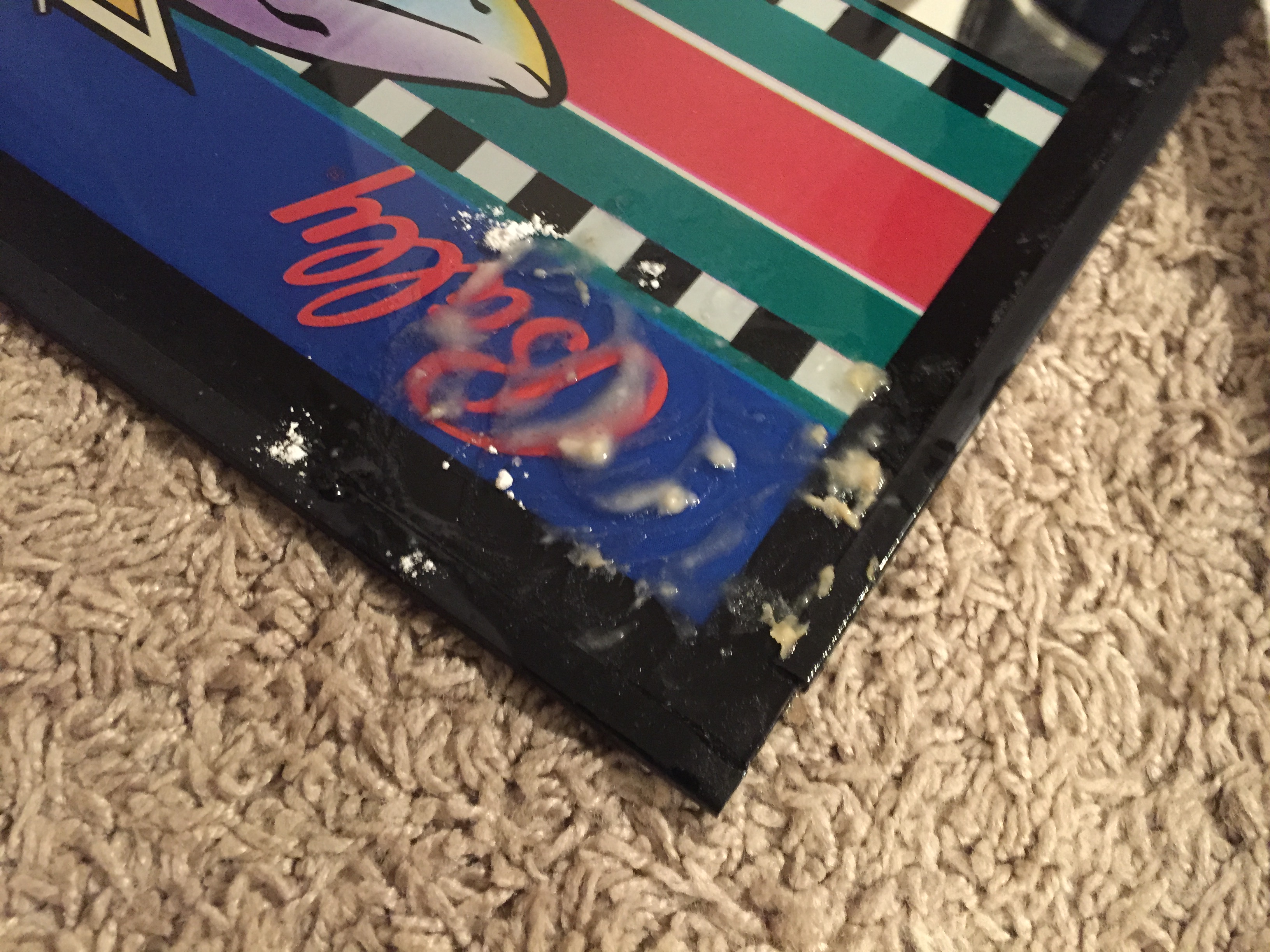
A 25-year-old sticker on a piece of glass can be a terrible pain to get off without leaving a
Removing residue with Goo Gone and flour.
mess behind. The method I use for best removal is to spray Goo Gone (NOT Goof Off) over the sticker, let it soak for about 5 minutes and then begin peeling up slowly. After the sticker is up, there is usually still a thin layer of glue residue. If you leave the Goo Gone on the glass and add a little normal baking flour to it and rub the flour with your finger over the residue, it’ll get the last of that sticky glue residue off the glass. Wipe up the Goo Gone with a paper towel, clean the glass with your preferred
Finished product — removed 25-year-old sticker. No residue left!
glass cleaner gently and viola, no remnants of that nasty sticker on your nice artwork.
I always check the battery situation on any game for corrosion first thing. This game didn’t have any corrosion on the board, but I noticed some green/blue corrosion beginning on the battery holder, so I cut that sucker off and added a remote pack. If you add a remote pack to your game, make sure to set the pack as far away from the board as possible. If you remote the pack and stick it up over the board or close to the side, it might not do much good in preventing future damage.
Remote pack placed outside the “Danger Zone”
I lucked out in this Pool Sharks being a Diamond Plated playfield. This was Bally/Williams clearcoat method that didn’t become popular until around 1992. In 1990, only a small percentage of games had the Diamond Plate (which is preferred for extra protection of the playing field artwork). To get a Diamond Plated System 11 game like this is a nice surprise, and this playfield is beautiful. I polished it with Novus 2, added new balls and put down a good, hard layer of wax.
Diamond Plated playfield in really nice shape after polish and wax.
I was able to play a couple games and go through some tests. There are a few bulbs out, a couple bad 555 holders I found, the Talking Shark solenoid is not working in test mode and I noticed a couple switches that need adjustment. All-in-all though, not really that much to go through.
I’ve never played Pool Sharks before buying it, but clocked about 5 games as-is on it tonight. It’s actually a lot of fun! I’m looking forward to getting everything 100% on it. Next steps include: repairing my talking shark, adjustment of switches that need attention, fully LEDing the game (I began tonight with what I had surplus on hand but didn’t get too far), adding super bands on the flippers, adding new drop targets, and tearing down and re-rubbering with white rubbers.
A few weeks ago I saw an ad pop up on the Charlotte area Craigslist for a “Pinball Machine for parts”. When I clicked it, I noticed it was a Sorcerer, which is a pretty popular title and a really fun System 9 game (probably my favorite of the three).
Ground plane and partial back box from original game (CPU pulled for bench testing at this point)
The game was sitting at the road, the backbox head was completely obliterated, but the bottom cabinet looked OK from the pics, the playfield was sitting in the bottom cabinet, boards were attached to the ground plane and the backglass was still there. For what the seller was asking, I figured it’d be worth it just for the backglass (which looked really nice) and I could part the rest of the game out and sell off pieces to those that needed it, as well as keep some for games in the future in my stock.
I was at work, so I called my go-to pinball hauler (my brother Patrick), who goes to school during the week at UNC-Charlotte, and asked him if he would be willing to buy the game and pick it up for me for a little cash; luckily, he was interested. After his night class finished up around 9:30pm, Pat went and picked the game up from the seller near South Park. He got the game back to my house at nearly 11:45pm that night, and we unloaded it into my garage.
Upon seeing the game the first time, I thought what a shame it was to be a parter. The backglass was perfect, the boards looked in really good shape, and the playfield was nice too for its age. There’s some insert wear, but for an un-mylared game from this era with no clearcoat, it’s held up surprisingly well. Not to mention, it has perfect pop bumper caps and no broken plastics (almost unheard of for this title).
Playfield assembly sitting in my gameroom waiting for its fate to be determined.
Patrick told me the woman he had picked the game up from had told him that she bought it about 15 years ago (I ended up finding the receipt in the cabinet later, it was purchased in 2003 along with a Ms. Pac-Man arcade), and that her and her husband were moving it to their new house when it fell out of the back of their truck. This is what led the game to its unfortunate present condition.
A couple of days passed, and I continued to ponder what to do with this game, I became more and more determined to save it if I could. However, where was I going to find a full cabinet? Turns out, the bottom cab was split pretty bad too in the back, and the coin door was mangled really bad, so it would take a full cabinet to save this game.
I put out some feelers on http://www.pinballbash.com and http://www.pinside.com. I had some promising leads, but they were primarily either for part of a cabinet (bottom or backbox head), a head/bottom to another game of similar era which I would have to strip, sand and stencil, or hundreds of miles away. In the meantime, I bench tested the CPU which booted properly. The CPU booting got me even more on board to save this game.
As fate would have it, I ended up finding a cabinet less than 15 miles from my house! In speaking with one of the other local pin techs on the phone one day, he told me he had two Sorcerers. One he was keeping for himself, and one in lesser condition that he was planning to use to help make his primary game better. I immediately asked if I could buy the cabinet from his second game off him and explained my game’s situation.
The loaner cabinet I bought.
It took a couple weeks of persuasion, but Jack saved the day and ended up selling the cabinet to me. Overwhelmed with excitement, I ended up spending the majority of the day today pairing cabinet with parts.
Several of the boards had bent or broken pins I had to repair, and I spent a lot of time using the manual and checking pictures I took of the original ground plane to cross check connector pairings on the boards. Once all the boards were in and connectors put back on, I got ready to plug the game in and noticed the ground prong was broken off the AC line cable.
This is actually fairly common and I keep a good deal of three prong connectors around for just this situation. It’s an easy fix, just cut off the old head, use an exacto knife to trim back the rubber insulation, cut the paper-like insulation, and strip the green, black and white wires. The green (ground) wire goes to the green terminal on the new head, the black (hot) wire to brass terminal, and white (neutral) to silver terminal.
Three prong plug before I screwed in insulating back shield.
Outside of the CPU, I had no idea what to expect from the rest of the boards and other electronics. Seven digit displays are expensive for these games and I had no idea what kind of condition these would be in. One had some chips on it from the truck fall, so I was very concerned about it. I held my breath upon first boot up and, luckily, no pops or awful sounds came from the game; however, it did go directly into bookkeeping mode.
For System 9 games, this brings up the game’s code in the player one window (I think it was 5302 1 for this game) and some digits on the credit/match display, but that’s it. I had installed a remote pack in this game and put in some lithium batteries for the pack. I think the lithium batteries operate at a slightly higher voltage than the standard 1.5 volts a AA normally should, as it tested 5.2 or something like that. I’ve actually had a couple of these pre-System 11 era games not seem to like that at all, so, I put in some regular AA batteries and that got us the normal boot up.
Two issues I noticed at this point was missing sound, and when I coined up a game the K1 relay started engaging endlessly and flashing the GI circuit. Luckily, the sound issue ended up being a connector I had overlooked from the volume control that was sitting down in the bottom cabinet. Plugged that in and that knocked out the sound concern.
Boards in!
The K1 relay issue ended up not having anything really to do with K1, but rather a burnt up transistor for the drop target reset solenoid that caused all the drops to stay down and engage points/GI flashes. I ended up having to replace the TIP 102 and 4401 pre-driver transistor for that solenoid. Before installing the CPU, I had done a “quick and dirty” test of the transistors (checking continuity to ground from the tab on the TIP 122s), but overlooked the burnt trace on Q50 which drove this solenoid.
Once CPU was back in, I had a few switch adjustments to make and lights to replace, but all-in-all the game worked! Now that everything is working on it, I’ll invest the last little bit to fully get this game to where I want it.
My last bits of business will be to: troubleshoot one line out on player 2 display, buy two display mattes for player 2 and player 4 that were gone from the truck fall, buy all new star posts, rubber kit, drop targets, stand up target decals and lane change plastics and finish cleaning it all up and do one more layer of wax (I did a light shop on it today, wax, new balls, just to protect the playfield while I was testing).
Great feeling to know that a game that would have ended up a parter is back in line to doing what it should be — getting played!
I picked up a 1977 Bobby Orr Power Play about a month ago. It hadn’t booted properly in years and had been “dead” at one owner’s house, sold and then “dead” at the other owner’s place for a long time. The gentleman I bought it from was planning to get it up to speed, but just never got around to it. So, the game was need of a decent amount of attention.
The MPU on these games and the later Bally -35 (Stern boards from this era too) all had Ni-Cad rechargeable batteries directly on the MPU board. If these weren’t snipped off many years ago (and most haven’t been) then the board is usually covered in a nice layer of corrosion from the leaking battery. I’d say 50-75% of these games I run into have some level of corrosion on the board, whether they are working or not.
This game had what I would consider moderate corrosion; I usually won’t invest the time into severe corrosion clean-up as it is a timely process and there are replacement boards for these games available, albeit at a nearly $200 cost.
The usual areas affected, the reset section, LED and Q2 transistor area, and bottom ground plain all had corrosion damage. When booted, the LED light was “locked on” which is fairly common on a corroded board, and signifies that board is not getting through the boot-up process at all. When working properly, the LED on the board should flash seven times, six if you are on a test bench with just +5vdc, +12vdc and ground power.
Surprisingly, there wasn’t corrosion up under the sockets of the 5101 and U11 6821 PIA, but I did have to remove the complete reset section and everything below those chips. I sanded the board down to bare copper on the front and back, neutralized with a 50/50 vinegar/water solution (the corrosion is actually a base, so it takes an acid to neutralize) and re-populated the removed components.
Upon power on the bench, I got the needed six flashes. Took it out to the game to test the displays and see where that stood, and got all seven and a proper boot-up. I will still need to add a remote battery pack and re-tin the bare copper traces on this board.
This game still needs work as it has been sitting for a long time. Upon boot up, I could hear that the chime unit will need some attention, and I’m sure some other mechanisms will need work done as well.
In addition to fixing everything, I’m going to shop it out with new white rubbers, balls, clean plastics and playfield, wax playfield, new star posts, new pop bumper caps, new drop targets, LEDs in the GI and super bands. So, stay tuned as I continue work on this game. Once completed, it should be a pretty decent game for someone. This one will be for sale when complete.
1977 Bobby Orr Power Play, test boot in game to check displays.
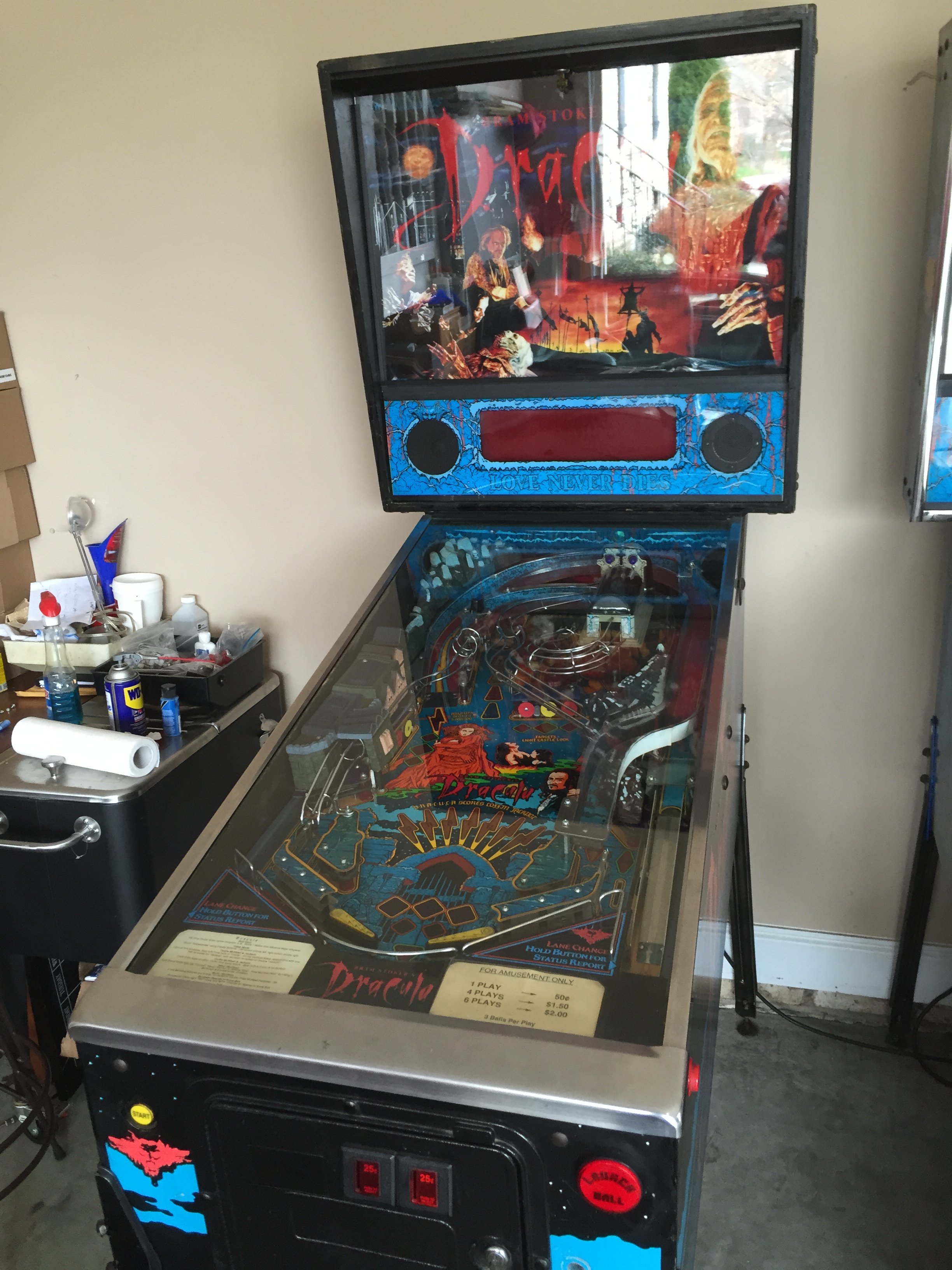
One of my pinball buddies picked this game up from an operator where it had been sitting for some time. It was cosmetically really nice, and actually the boards were quite clean as well. Just needed a few minor things to get up to speed.
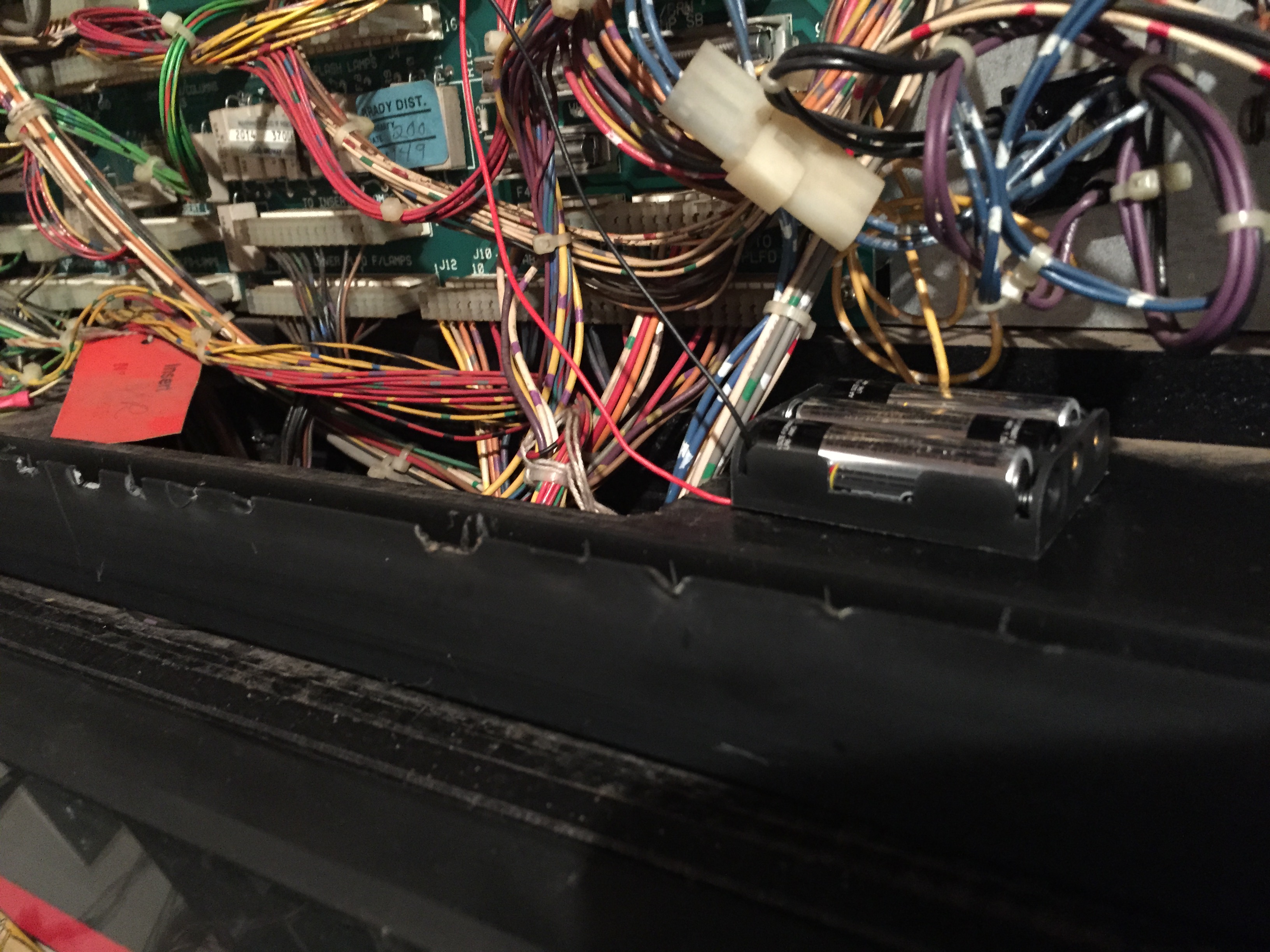
At some point, the speaker wires had been cut. I stripped those and soldered them back on which got the sound back up and running. The “Love Never Dies” flash lamps weren’t working either due to some wires that had come out of the IDC connector. I hate IDC connectors, so I replaced this with a molex .156 female connector and crimped in the wires with trifurcon terminals.
The display that was in the game was dead, so we replaced it as well. The game was having a reset issue when both flippers were pushed, which is actually really common on WPC games after 20 some odd years. There’s a long list of things to check when WPC resets start happening, the most extensive and thorough I’ve found can be found here on the PinWiki: http://pinwiki.com/wiki/index.php?title=Williams_WPC#Game_resets
This game had good line voltage, thermistor, AC cabling, seated connectors, etc. We got
BR2 and C5 replacement before heat sink over bridge rectifiers added back.
down to the BR2/C5 replacement. I replaced both and ran jumper wires to strengthen the connection, which cleared up the reset issue.
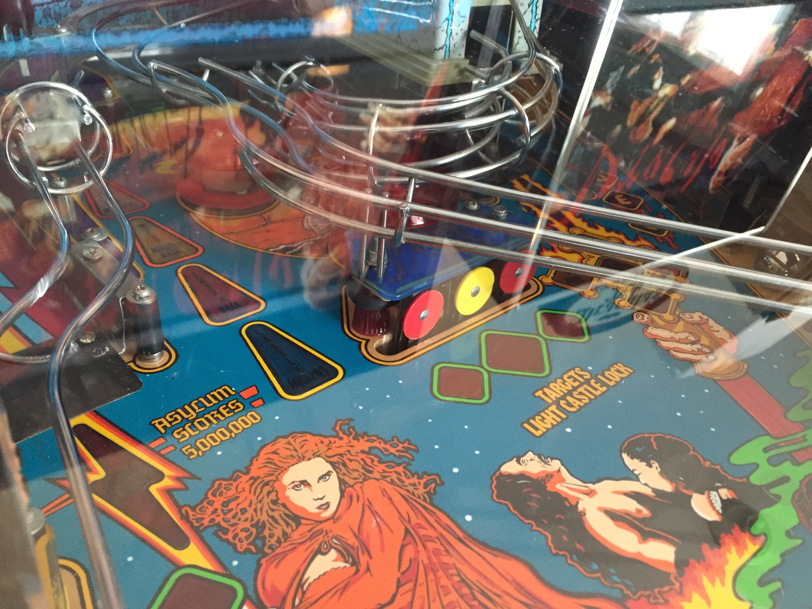
On BSD, the center three drop targets are supposed to all be round targets. However, at some point, this game had two oblong targets put in for the outer two. So, I soldered in two round targets to match the original game spec properly.
The last issue we noticed were a couple rollover switches not registering. Most of the time these micro switches aren’t actually broken, just need some adjustments. When adjusted properly, you should here a little click when they are depressed. Always test with a ball, however, as sometimes you can get the rollover to register with your hand but it might not with a ball traveling over it. Occasionally, it takes multiple adjustments to get these switches just right and, sometimes, even if the switch isn’t faulty per se, it might still need replacement. The original part for these rollovers with Cherry DA3, but that part is now obsolete, so if you replace use Cherry DB3.
Replaced oblong targets with round targets.
That wrapped everything up on this one. Bram Stoker’s Dracula is a brutal pinball machine, but when you master the stacked multi-ball it can be a real blast. I owned one for about 6 months before trading for a Shadow, and wouldn’t be opposed to another one day down the line.
Picked this one up for the personal collection a couple weeks ago from an operator in Asheville, NC. Overall, it was in pretty good shape, but I’ve been dialing it in and bringing it up to my picky standards.
Nothing really major wrong with the game from a playability perspective, just a lot of adjustments, cleaning up and I wanted to convert to LED lamps throughout. There were two switches not registering properly, one up near the magic bus on the upper ramp and the other at the entrance to the dog house.
After years of use, these little microswitches can get bent to staying in the closed position at all times, not closing all the way or being mangled to where a ball won’t travel over or under properly. 95% of the time there is nothing physically wrong with the microswitch, the blade just needs to be adjusted for consistency, though finding the right “sweet spot” can take several attempts sometimes. For both of these switches, it was just minor adjustments.
The game when I got it had all incandescent lamps in it, and unless you buy a game from a collector, the likelihood of a game having anything other than this is slim. I prefer the look of LEDs personally, though it’s not for everyone. Even for me, there can be what I call “too much” with an LED scheme. I don’t want it to look like a Christmas tree or blind people when they walk up to the machine, so I try to do what I consider a tasteful design when LEDing a game. I also like that LEDs run cooler and draw less amperage than incandescent lamps, which is less stress on the boards and reduced chance of heat damage on inserts or plastics.
I’ve tried all the major LED suppliers in the past, and my go-to LED supplier is Comet Pinball (www.cometpinball.com). Art, the owner, is a great guy and his pricing, selection and customer service are the best in my book.
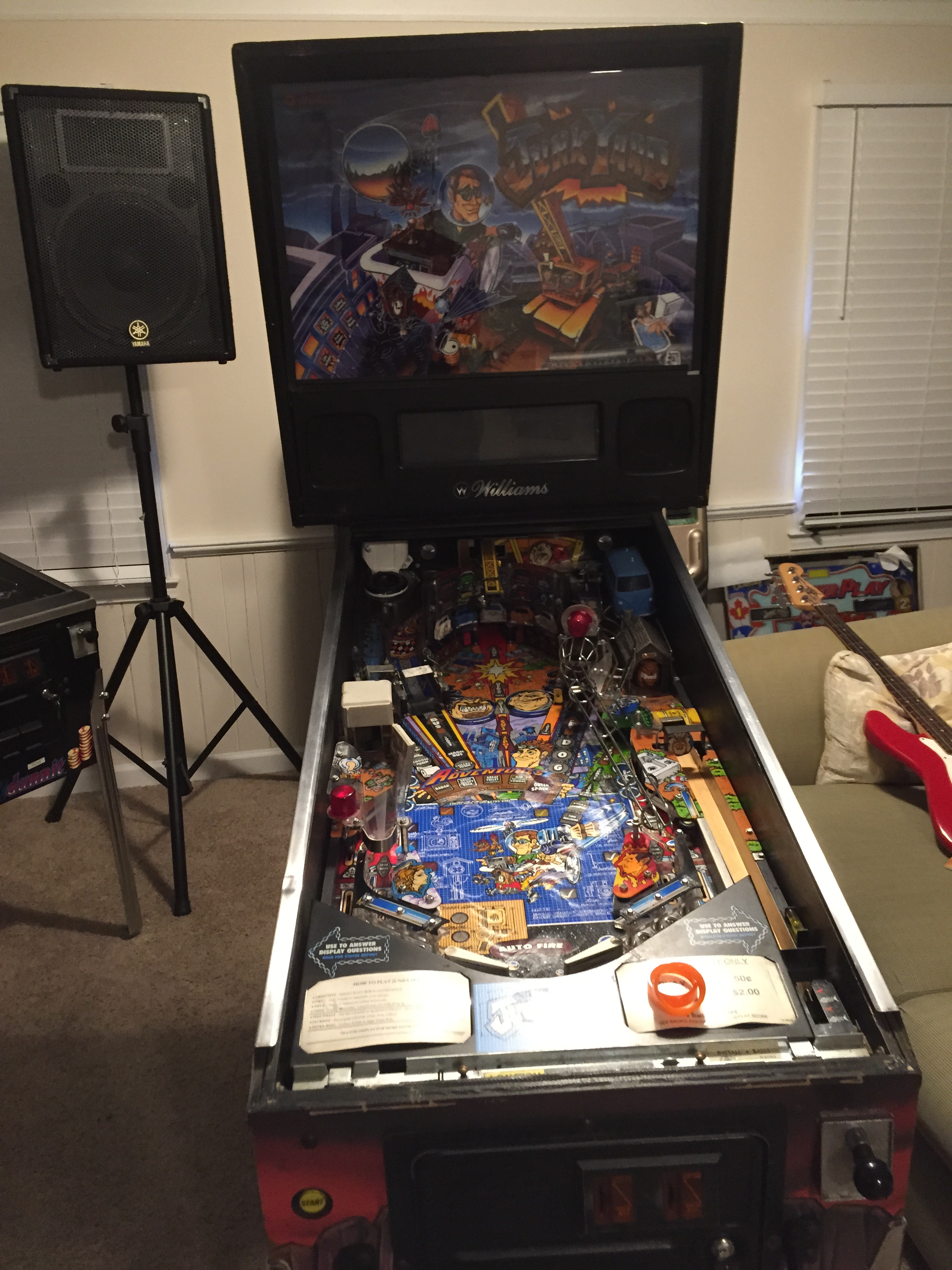
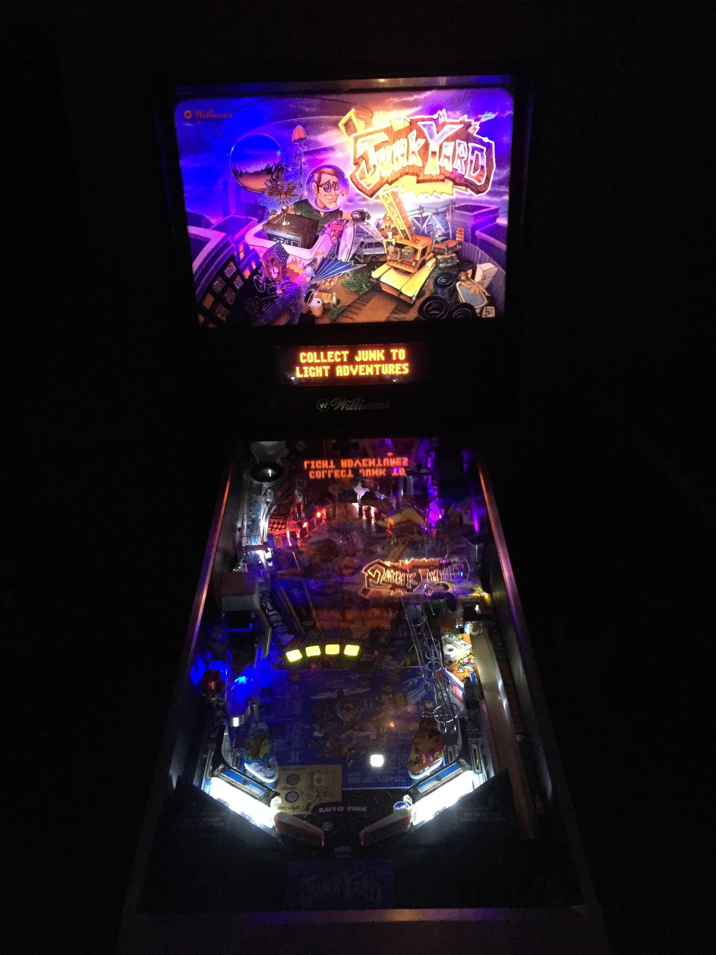
Completed LED conversion on Junk Yard Pinball Machine.
With most games I bring into my personal collection, I do a full tear down shop job on them. For this Junk Yard, however, the game had been “shopped”, just not quite to where I like it. So, all the white rubbers are in good shape, but it could use a little cleaning up around the edges. Since full tear down shops take a lot of time and this one was about 80% the way there, I just did a light clean up on it and waxed to protect the field for future play. I usually try to wax my games every 125-175 plays.
Like all Junk Yards, the wrecking ball plastic was cracked on this one, which I have ordered a replacement from Little Shop of Games. It also had one other broken plastic near the Jackpot hole that I was lucky enough to find an NOS (new old stock) replacement from Australia. I’ve also got the auto plunger bracket on order as the original had worn and sags, causing the shooter rod to not fire perfectly.
As soon as the last of my orders is in, this game will be 100% done and good to hit the line up. I’ve already got a sale pending on a 1995 Who Dunnit, who’s place Junk Yard will assume.
I recorded a video of this repair since I thought it might be helpful for some of you guys. I’ve attached the YouTube link of the video at the bottom of the page which goes through a, more or less, step-by-step of the process.
My Tommy has a repro servo board on it, though I still have the old board and think it is OK as well, just the R2 and R5 pots are a little beat up.
Anyway, since the game came with the repro board, that’s what I left in there. It’s cleaner than the old board in layout and has 19 years less use time on it which I’m sure is not a bad thing. I thought the culprit with the blinders not working was the servo motor, and it turns out, I was right on this one.
The old motor would run, but not move the link arm which points to a high likelihood of stripped gears. These little servos are extremely simple and work off of very tiny plastic gears that move in conjunction to swing out the link arm. Over time, and I’m going to go out on a limb and say this one was from the factory, these little gears get worn down and the servo needs to be replaced.
So, I ordered an Airtronics 94102 servo motor to replace the bad one. Several of the pinball parts companies online carry this unit, but have a pretty decent little markup on the price. If you Google “Airtronics 94102” you should be able to find the exact same servo for about half the price from an RC hobby shop.
The most important thing I learned was that the new “Z” connector isn’t as plug-in-play as I originally believed. According to Marco’s, they have an installation note saying the blue wire is the 5v, the red the ground and the black is the signal wire, which would in theory make the servo plug-in-play. However, I found out that that’s not exactly correct after some frustrations with the installation.
The blue wire is actually the signal wire, the red is the 5v and the black is the ground. Their alignment in the “Z” connector will not work with the Tommy servo board, old or repro. So, what you have to do is unpin the red and black wires and switch them so that red will run to the 5v, black with be ground in the center and your blue wire will take the signal feed. There’s a good PDF available online I found which helps explain the difference between the old Airtronics 94102 and new “Z” connector style that has replaced it here: http://jacobwatson.com/images/dads%20images/connectors.pdf.
Other than that, everything was pretty straight forward and just took some careful adjustments. I’m happy to report that I now have working blinders on my Tommy!
As strange as it sounds, I think I need to get a cheaper camera to document some of these repairs. Using what I normally use for some of my freelance gigs, though the picture quality is nice, the no auto focus ability and super shallow depth of field was a bit difficult to work with while trying to do a “how to” by myself. So, apologies on any part of the video that maybe snuck out of focus here or there. Anyway, here’s the video that documents this repair a bit more extensively:
Just as a note, before I put the apron on, I ran the little servo wiring up through the playfield hole to make it a little tidier before putting everything back together.
I’ve got two repairs I’ll be doing on Tommy this weekend. One is pretty minor, and the other isn’t major, but a little bit more intricate. For the second, I will add a video of my progress in case it is valuable to anyone else with the same problem.
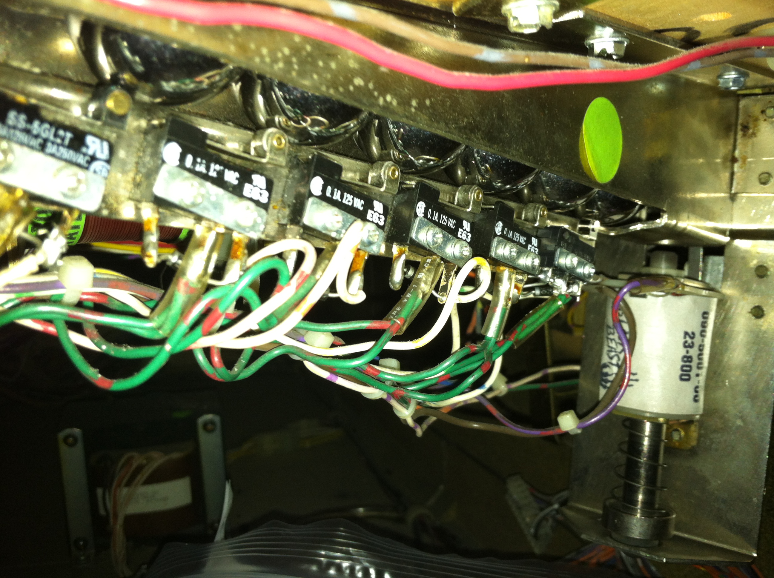
For this fix, however, I will just snap a few pictures and try to walk you guys through the problem and the solution. The other day, I was playing Tommy and some odd things started happening: Jackpots continued in multiball mode even once I was down to one ball, and then when it drained, it didn’t go into the end of ball bonus phase. With a little nudge, the sixth ball was recognized finally, but once the bonus was calculated the next ball shot out two balls rather than one. I knew immediately that I had a trough issue on my hands as all of these signs are classic examples of ball trough issues.
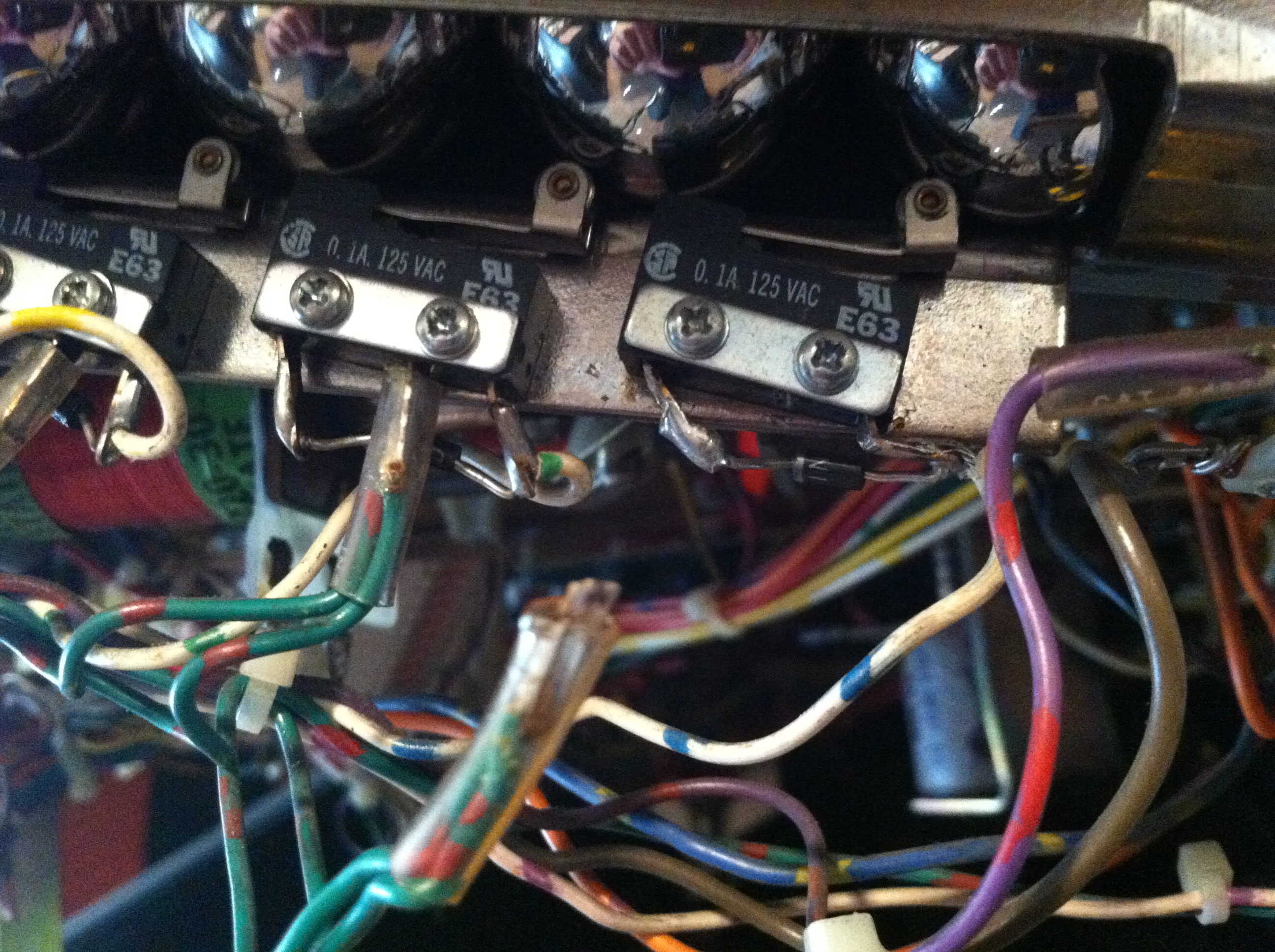
The middle lug broke off the furthermost trough rollover switch.
Sure enough, when I lifted the playfield, I noticed the furthermost trough switch had an problem. At first, it looked as if the double-wired positive green-red line had simply come desoldered from the middle lug; however, upon further inspection, the entire middle lug had come off!
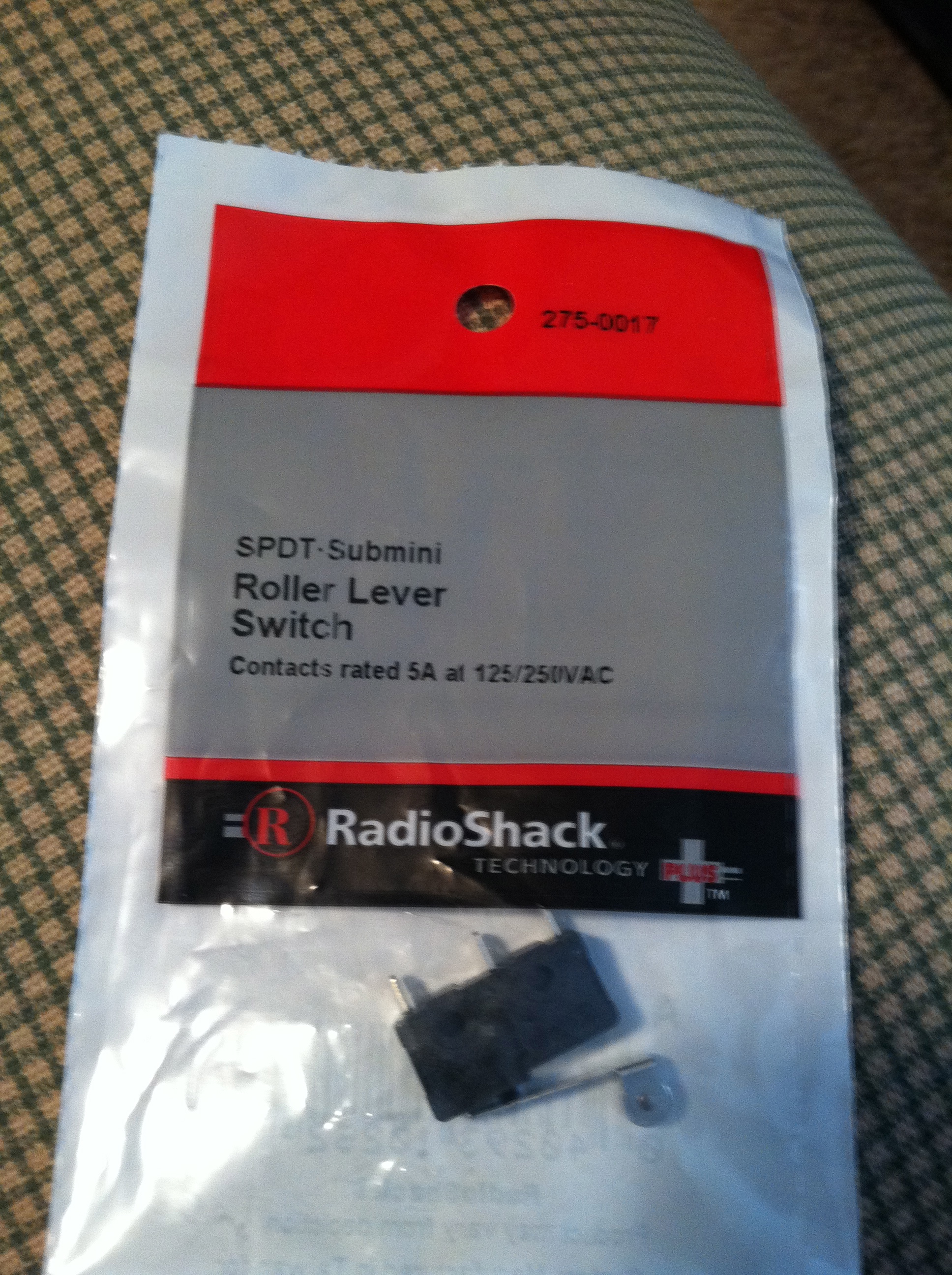
Radioshack conveniently carries a suitable replacement! Part #275-017.
Luckily, Radio Shack carries an equivalent part in stock, so I didn’t have to make an online order with one of the many online pinball parts companies and wait for a few days before tackling this issue. The part at Radio Shack is part #275-017. I picked up two, just to have one more on hand.
As you can see in the picture, the middle lug came completely out. With a small phillips head screwdriver, I took out the two screws holding the trough switch in. After that, I desoldered the blue-white ground wire from the rightmost lug. At this point, just take note of the orientation of the N4001 diode that is soldered between the outer two lugs, and then disregard the old switch/diode.
I could have probably salvaged the old diode, but with as cheap as they are, I just used a new N4001 blocking diode. I soldered it in array on the outermost lugs, same orientation as the rest of the switches, which was banded side towards the leftmost lug if you are looking at it as it is oriented in the machine (side without the white-blue wire). After that, I soldered the white-blue wire onto the right lug (non-banded side) and then soldered the double green-red wire onto the middle lug.
The finished product! (Insulator tubing pushed up all the way after this photo was taken.)
With the new switch, it might need to be adjusted a bit to fit the screw holes and still register when the balls are over it. Screw in the two holding screws and make sure the switch is engaged (clicked) when balls are resting on top of it. If you can press the switch and hear a click when the balls are resting over it in the trough, you need to take it out and re-adjust.
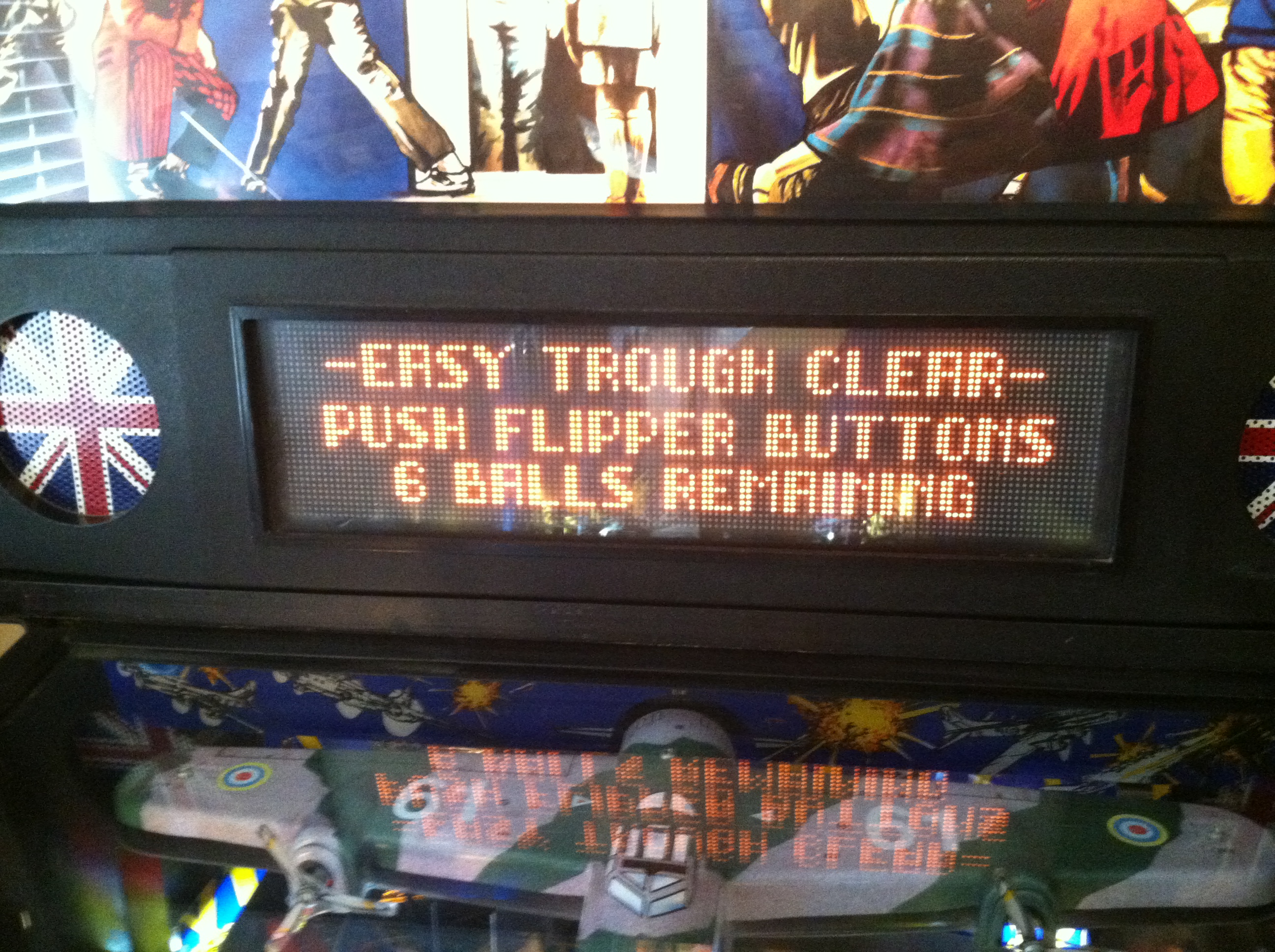
All six balls registering properly! One fix down, one to go!
I fired up the game, no “Pinball Missing” error message on the screen. Went into diagnostics just to double check (this can be confusing on DE games sometimes. Push the green push/pull in so it is engaged, do it on both green push buttons if there is a double set of knobs on the coin door, and then press the black button). In diagnostics, as hoped, all six balls were registering. I fired up a game, and everything worked perfectly.
One fix down, and one to go! My other issue is the Tommy blinders weren’t working when I got this machine. The previous owner bought a new board, but I don’t think the board was really the issue on this one, though an update over the 19-year-old original board is definitely not a bad thing! I think the servo motor has stripped gears. I’ll probably be doing that fix tomorrow, so tune in for a video of if my theory is correct as I install a new Airtronics 94102 servo into the blinder mech on Tommy!