A few weeks ago I saw an ad pop up on the Charlotte area Craigslist for a “Pinball Machine for parts”. When I clicked it, I noticed it was a Sorcerer, which is a pretty popular title and a really fun System 9 game (probably my favorite of the three).

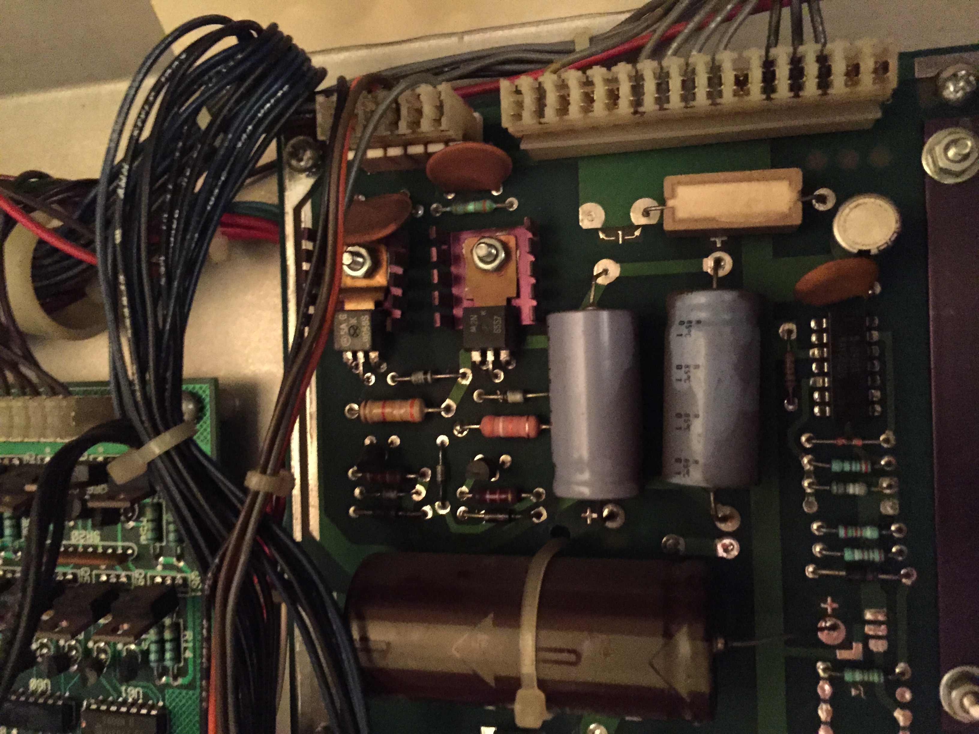
Ground plane and partial back box from original game (CPU pulled for bench testing at this point)
The game was sitting at the road, the backbox head was completely obliterated, but the bottom cabinet looked OK from the pics, the playfield was sitting in the bottom cabinet, boards were attached to the ground plane and the backglass was still there. For what the seller was asking, I figured it’d be worth it just for the backglass (which looked really nice) and I could part the rest of the game out and sell off pieces to those that needed it, as well as keep some for games in the future in my stock.
I was at work, so I called my go-to pinball hauler (my brother Patrick), who goes to school during the week at UNC-Charlotte, and asked him if he would be willing to buy the game and pick it up for me for a little cash; luckily, he was interested. After his night class finished up around 9:30pm, Pat went and picked the game up from the seller near South Park. He got the game back to my house at nearly 11:45pm that night, and we unloaded it into my garage.
Upon seeing the game the first time, I thought what a shame it was to be a parter. The backglass was perfect, the boards looked in really good shape, and the playfield was nice too for its age. There’s some insert wear, but for an un-mylared game from this era with no clearcoat, it’s held up surprisingly well. Not to mention, it has perfect pop bumper caps and no broken plastics (almost unheard of for this title).

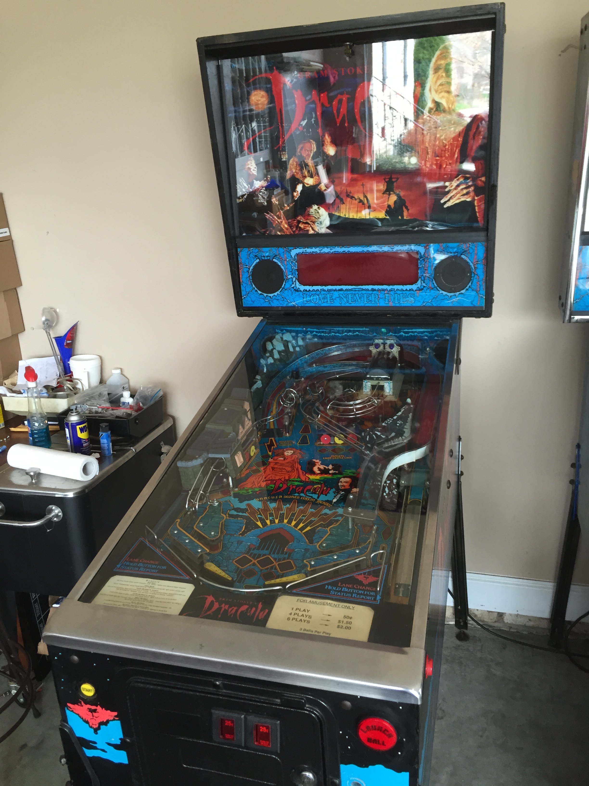
Playfield assembly sitting in my gameroom waiting for its fate to be determined.
Patrick told me the woman he had picked the game up from had told him that she bought it about 15 years ago (I ended up finding the receipt in the cabinet later, it was purchased in 2003 along with a Ms. Pac-Man arcade), and that her and her husband were moving it to their new house when it fell out of the back of their truck. This is what led the game to its unfortunate present condition.
A couple of days passed, and I continued to ponder what to do with this game, I became more and more determined to save it if I could. However, where was I going to find a full cabinet? Turns out, the bottom cab was split pretty bad too in the back, and the coin door was mangled really bad, so it would take a full cabinet to save this game.
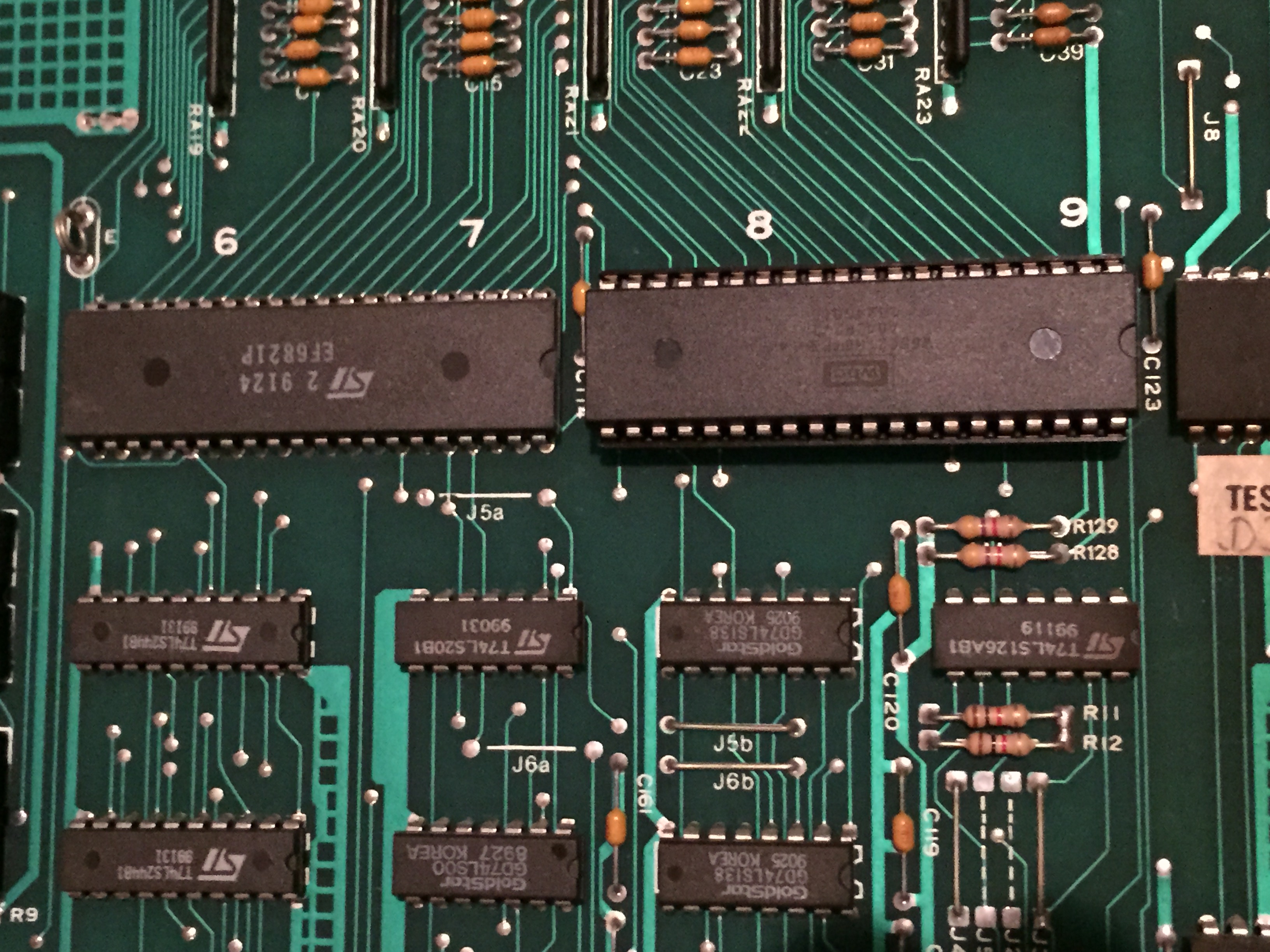
I put out some feelers on http://www.pinballbash.com and http://www.pinside.com. I had some promising leads, but they were primarily either for part of a cabinet (bottom or backbox head), a head/bottom to another game of similar era which I would have to strip, sand and stencil, or hundreds of miles away. In the meantime, I bench tested the CPU which booted properly. The CPU booting got me even more on board to save this game.
As fate would have it, I ended up finding a cabinet less than 15 miles from my house! In speaking with one of the other local pin techs on the phone one day, he told me he had two Sorcerers. One he was keeping for himself, and one in lesser condition that he was planning to use to help make his primary game better. I immediately asked if I could buy the cabinet from his second game off him and explained my game’s situation.

The loaner cabinet I bought.
It took a couple weeks of persuasion, but Jack saved the day and ended up selling the cabinet to me. Overwhelmed with excitement, I ended up spending the majority of the day today pairing cabinet with parts.
Several of the boards had bent or broken pins I had to repair, and I spent a lot of time using the manual and checking pictures I took of the original ground plane to cross check connector pairings on the boards. Once all the boards were in and connectors put back on, I got ready to plug the game in and noticed the ground prong was broken off the AC line cable.
This is actually fairly common and I keep a good deal of three prong connectors around for just this situation. It’s an easy fix, just cut off the old head, use an exacto knife to trim back the rubber insulation, cut the paper-like insulation, and strip the green, black and white wires. The green (ground) wire goes to the green terminal on the new head, the black (hot) wire to brass terminal, and white (neutral) to silver terminal.

Three prong plug before I screwed in insulating back shield.
Outside of the CPU, I had no idea what to expect from the rest of the boards and other electronics. Seven digit displays are expensive for these games and I had no idea what kind of condition these would be in. One had some chips on it from the truck fall, so I was very concerned about it. I held my breath upon first boot up and, luckily, no pops or awful sounds came from the game; however, it did go directly into bookkeeping mode.
For System 9 games, this brings up the game’s code in the player one window (I think it was 5302 1 for this game) and some digits on the credit/match display, but that’s it. I had installed a remote pack in this game and put in some lithium batteries for the pack. I think the lithium batteries operate at a slightly higher voltage than the standard 1.5 volts a AA normally should, as it tested 5.2 or something like that. I’ve actually had a couple of these pre-System 11 era games not seem to like that at all, so, I put in some regular AA batteries and that got us the normal boot up.
Two issues I noticed at this point was missing sound, and when I coined up a game the K1 relay started engaging endlessly and flashing the GI circuit. Luckily, the sound issue ended up being a connector I had overlooked from the volume control that was sitting down in the bottom cabinet. Plugged that in and that knocked out the sound concern.

Boards in!
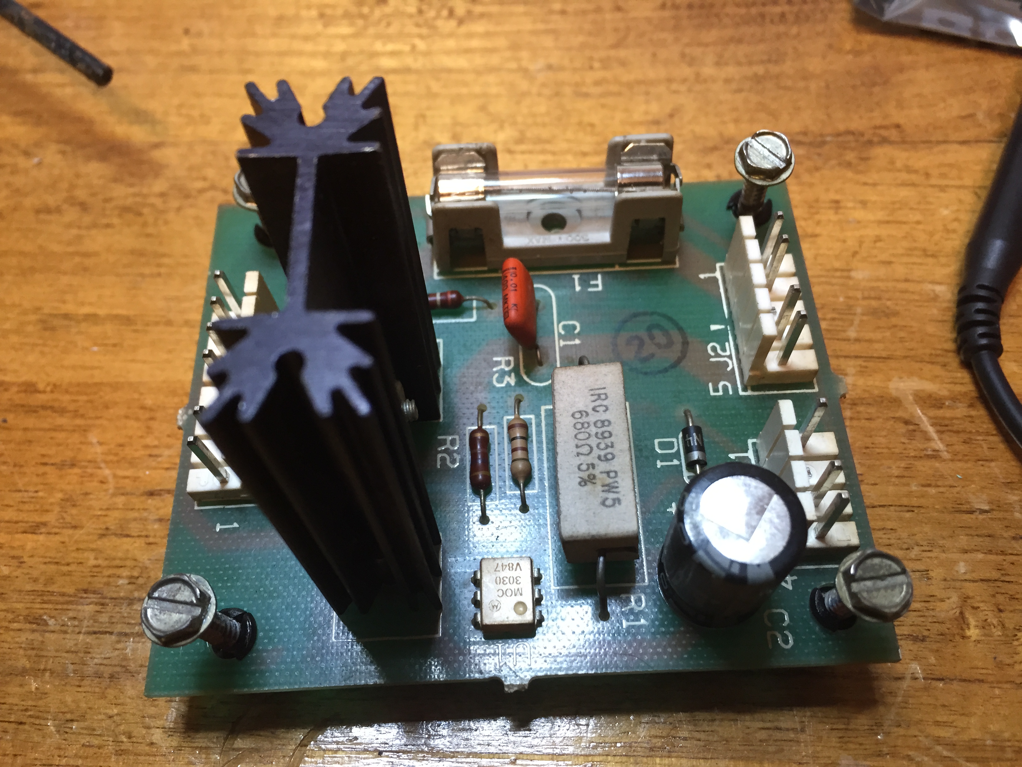
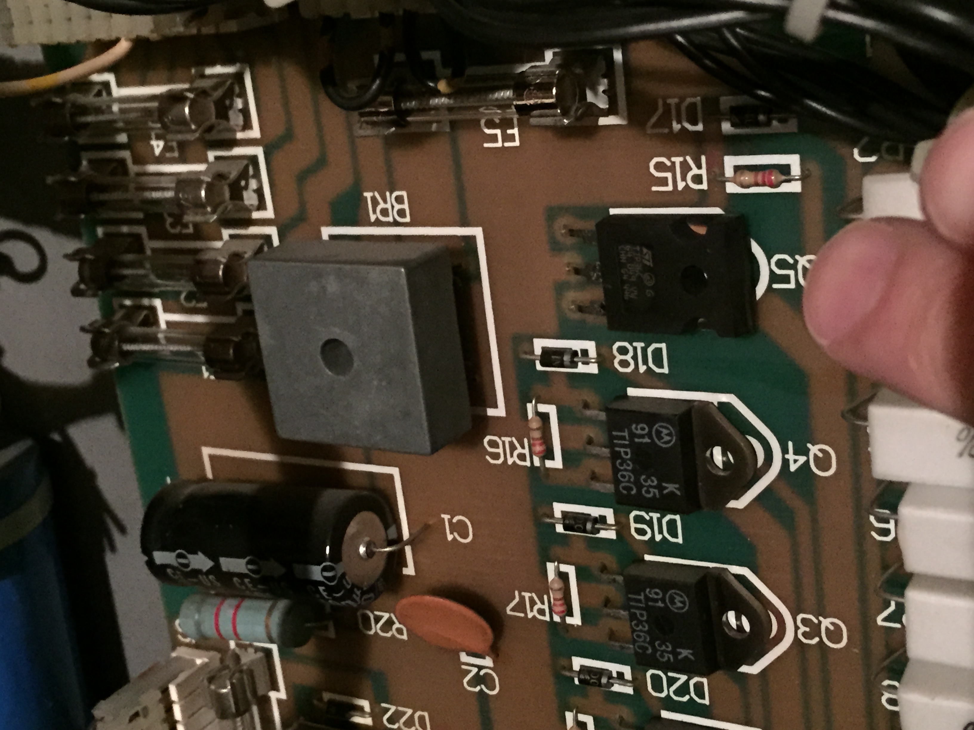
The K1 relay issue ended up not having anything really to do with K1, but rather a burnt up transistor for the drop target reset solenoid that caused all the drops to stay down and engage points/GI flashes. I ended up having to replace the TIP 102 and 4401 pre-driver transistor for that solenoid. Before installing the CPU, I had done a “quick and dirty” test of the transistors (checking continuity to ground from the tab on the TIP 122s), but overlooked the burnt trace on Q50 which drove this solenoid.
Once CPU was back in, I had a few switch adjustments to make and lights to replace, but all-in-all the game worked! Now that everything is working on it, I’ll invest the last little bit to fully get this game to where I want it.
My last bits of business will be to: troubleshoot one line out on player 2 display, buy two display mattes for player 2 and player 4 that were gone from the truck fall, buy all new star posts, rubber kit, drop targets, stand up target decals and lane change plastics and finish cleaning it all up and do one more layer of wax (I did a light shop on it today, wax, new balls, just to protect the playfield while I was testing).
Great feeling to know that a game that would have ended up a parter is back in line to doing what it should be — getting played!